Water is an essential resource that is often taken for granted. In many places, access to clean water is limited, and the monitoring of water levels in reservoirs, tanks and wells becomes crucial. A water level indicator is a useful tool that allows users to keep track of water levels, ensuring that they do not run out of water, or conversely, do not experience overflows. In this post, we will discuss how to build a Water Level Indicator using Ultrasonic Sensor, Arduino and PCB Design.

Circuit and Program Design:
The water level indicator is built using an ultrasonic sensor HC-SR04 mounted on the top of the water tank or reservoir. Ultrasonic sensors are widely used for distance measurement and can detect distances up to 400 cm. The sensor sends an ultrasonic pulse and receives an echo from the water surface, and the distance is calculated based on the time taken for the pulse to travel and return.
The circuit design comprises an Arduino UNO board, an ultrasonic sensor HC-SR04, a 16x2 LCD display, a resistor and a few jumper wires. The ultrasonic sensor is connected to the Arduino using four pins, VCC, GND and two pins for input and output data.
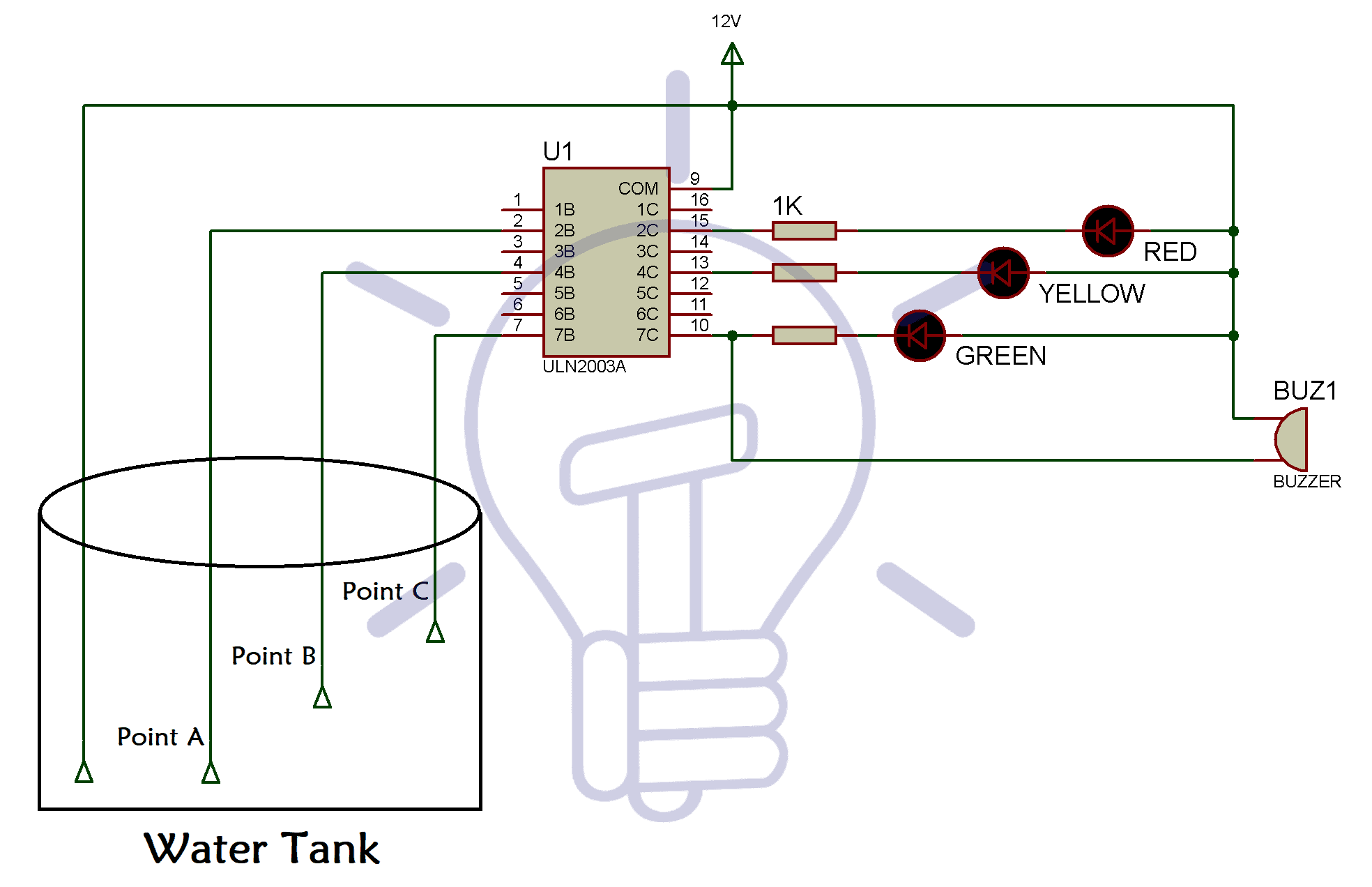
The circuit diagram shows the connections between the components:
[PIC]
* Connect the VCC of the sensor to the 5V pin on the Arduino board.
* Connect the GND of the sensor to the GND pin on the Arduino board.
* Connect the Trig pin of the sensor to the D2 pin on the Arduino board.
* Connect the Echo pin of the sensor to the D3 pin on the Arduino board.
The LCD Module is connected to the Arduino in 4-bit mode, i.e., using only four data lines. The backlight of the LCD display is connected to the 5V pin of the Arduino board, and the contrast pin is set through a variable resistor.
The code for this project is written in C language and compiled using Arduino IDE. The program uses the pulseIn() function to measure the pulse duration of the echo signal and calculates the distance of the water surface from the sensor. The distance is then converted to the water level in the tank. The program then displays the water level on the LCD screen.
PCB Design:
The PCB design is essential for any electronic project. It ensures that a project is neat, easy to maintain, and long-lasting. Here, we will design a PCB for our Water Level Indicator using Eagle software. The following picture shows the schematic design of our Water Level Indicator:
[PIC]
The Eagle software provides tools for drawing the traces, placing parts, and generating the board layout. The following picture shows the board layout of our Water Level Indicator:
[PIC]
The board layout includes the placement of the components, the placement of the traces, and the vias, which allow connecting the top and bottom layers.
Video Demo:
In this part, we provide a video demo of our Water Level Indicator using Ultrasonic Sensor. The video demonstrates the complete project, starting from the hardware setup to the final output on the LCD screen.
Conclusion:
The Water Level Indicator using Ultrasonic Sensor is a useful project that can be used to monitor water levels in tanks, reservoirs, and wells. It uses an ultrasonic sensor to detect the distance between the water surface and the sensor, and displays the water level on an LCD screen. The project includes the circuit design, program code, PCB design, and video demo. Important keywords in this article include Water Level Indicator Using Ultrasonic Sensor- Circuit, Program Code, PCB Design, Video Demo, and Arduino.
